Contents | About | Contact
article 02, issue 01
The Ventilation of Streamlined Human Powered Vehicles (condensed version)Ben Wichers Schreur
July 21, 2004Abstract
Streamlined Human Powered Vehicles are often poorly ventilated. This is most obvious from the heated faces of riders and the steamed-up windows of the vehicles during long duration races and record events. Rider overheating not only affects performance but can also pose a serious health risk. These consequences are avoidable as a well-designed ventilation system can provide adequate cooling without requiring much power.
The necessity of cooling and ventilation
The human engine operates within a narrow temperature range. An increase of the body temperature of only a few degrees leads to a strong decrease of performance. In an investigation of professional cyclists who could generate an average of a half horsepower (373 Watt) during a one hour race, it was found that they were only able to sustain that level for 5 to 15 minutes on a stationary bicycle ergometer operated indoors. A world hour record attempt in a state-of-the-art streamlined HPV requires similar power levels. Obviously adequate cooling is then required.
The thermal efficiency of humans is less than 25%. An effective power output of 373W therefore results in the production of at least 1119W of excess heat which has to be removed by cooling, i.e. by air flowing past the rider and by the evaporation of sweat. This leads to an increase of temperature and humidity inside the fairing.
The following expression for the airflow S required for cooling is derived in the full article.
[equation 1]
Here f is the efficiency, P is the rider's mechanical power, rho the air density, cp the isobaric heat capacity = 1004 J/kgK, T the temperature, L = 2.42 MJ/kg, e = 0.622, p the atmospheric pressure, rh the relative humidity, and es the saturation vapor pressure, which can be looked up in the spreadsheet file. The index i indicates the conditions within the fairing, the index o the environmental conditions.
The effect of various conditions can be studied by programming the equation for the cooling airflow in a spreadsheet. As an example the airflow S for typical conditions To = 15°C, Ti = 25°C, rho = 60%, rhi = 80%, p = 101325 Pa, P = 373 W and f = 0.25 is calculated to be S = 28 liter/s.
![[figure 1] screen capture of spreadsheet](spreadsheet.gif)
[figure 1] screen capture of spreadsheetThe warm humid air in the fairing will have a tendency to condense when it comes into contact with a cool window. With the preceding airflow calculation the relative humidity at a window with T = To is found to be
[equation 2]
Condensing water vapor will fog up the window unless this is prevented by direct ventilation of the window with unsaturated air.
The liquid that is removed by ventilation is produced by the athlete. In the given example the rider loses 1.15 liter of fluid per hour. An adult human can tolerate a fluid loss of about 1.5 liter. Larger losses will quickly lead to a performance loss.
The power required for ventilation
The additional drag on the HPV results from the internal ventilation flow and the accompanying losses.
The ventilation of a streamlined HPV requires power D x V which is derived in the full article to be:
[equation 3]
where D is the drag, m the mass flow, V the velocity of the vehicle, Aex and Ain the cross sections of the exhaust and input ducts, respectively.
From this equation it follows that the amount of power required for ventilation can be minimized by restricting the airflow to the minimum required by cooling and by making the exit duct small and the input duct large. This equation also indicates that the maximum power lost to ventilation under the conditions used in the previous calculations and at a vehicle velocity of 80 km/h is D x V = m x v2 = 14W. The power loss is thus limited even in the worst case. If the input and exhaust ducts are of the same size, the loss here would be 14W x 0.29. It should be remarked that here only internal flow losses are taken into account. See the last section of this article for considerations of the losses due to the disturbance of the external flow.
The internal losses are predominantly dictated by the flow velocity within the fairing. It is beneficial to keep this velocity as low as possible. In practice there are two important limitations to the size of the intake: the allowable disturbance of the external flow (see below) and the minimum airflow velocity around the body of the rider that is required to achieve efficient evapotranspiration and cooling. Assuming a minimum internal velocity of 3 m/s, a cooling surface of 1.8 m2, and the values form the previous calculations, we arrive at duct sizes leading to a ventilation power loss of only D × V = 0.15 W. This loss is minimal and there is no reason to deny the rider adequate cooling and ventilation, provided that care is taken in the design of the ventilation system, in particular to avoid unwanted disturbances of the external flow.
Design considerations
In the previous sections it has been demonstrated that the power required to provide adequate cooling is in all cases small, even with a disadvantageous ratio of the intake and exhaust sizes. However the external losses must also be minimized with careful design of the ducts.
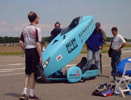
[Figure 2] This magnificent tricycle of Jürg Birkenstock has a so-called 'NACA submerged duct' for ventilation. On the photograph the duct is the dark triangle in front of the window. This placement of the intake ensures that the ventilation air is aimed directly at the rider. (photograph courtesy of Robert Biesemans, 2001.)
Placement of intake and exhaust
The best choice for the placement of the exhaust is at the back of the vehicle, where the ventilation air is blown out backwards directly into the vehicle wake. If the flow velocity in the wake is noticeably lower than the free stream velocity the injection of ventilation air at practically the free stream velocity may even lead to a drag reduction.
The intake velocity must be low. Because the external flow near the stagnation point at the front of the fairing already has been retarded, the immediate surrounding of the stagnation point is the obvious place for the intake. There is then no need to slow down and thereby disturb the flow at some other point on the fairing. As an alternative to a stagnation point intake sometimes a so called ’NACA submerged duct’ is used.Figure 2 gives an example of a NACA duct on an HPV. Such an intake sucks in the ’dirty’ boundary layer air.
Apart from the intake and exhaust, the fairing has to be airtight to avoid unintended outflows and disturbances. Extra openings for the ventilation of the window should be avoided. It is better to tap the windscreen ventilation air from the stagnation point intake.
Size of the intake and exhaust
The minimum size of the intake can be calculated from the required volume and speed range of the airflow. The minimum speed of the airflow was given above to be 3 m/s. Using values from the previous examples the minimum cross-sectional area of the intake is 28cm2, corresponding to a diameter of 6cm.
The optimal size of the (ideally variable) exhaust can be calculated from the fixed size of the intake using the equations given above and is found to be of the same order as the intake.
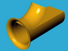
[Figure 3] Principal design of a stagnation point intake. Properties are a well-rounded inflow edge, a smooth finish of the inner surfaces and a split of the intake in a small window ventilation channel and a larger cooling air channel.
Shape of the intake and exhaustFor the ducts to be effective, they must have the right shapes. Sharp edges on the inflow side of the air channels will cause flow separation and choke the channel. The inflow edges of the intake and exhaust must therefore be sufficiently rounded. Sharp bends and obstructions should be avoided. The air channels should be hydraulically smooth to avoid the build-up of a thick boundary layer.
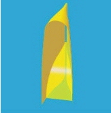
[Figure 4] Principal design of an exhaust. The ventilation flow is accelerated through a smooth constriction in the tail of the fairing and blown out with the highest possible velocity into the wake.
A sketch of an intake conforming to these principles is given in figure 3.
Figure 4 suggests how a smooth constriction in the tail of the fairing can be used to accelerate the internal ventilation flow to almost the vehicle velocity before it is blown straight backwards into the vehicle wake. In this sketch the exhaust is placed at the top of the tail, because this shortens the route from the head and shoulders, where the ventilation is aimed at, to the exhaust, thus limiting the internal flow losses.
Directed cooling and ventilationThe need for ventilation can be limited by using it as effectively as possible. The airflow therefore should be directed at the head and shoulders of the rider, as those are the prime areas of the body for heat exchange. This can be achieved by connecting the intake with a tube that ends near the rider’s face. Finally as has been demonstrated before, part of the ventilation flow will have to be directed at the window to avoid condensation.
Download the complete article PDF (140 KB)
Download the supplemental spreadsheet XLS (27 KB)